Level of Development (LOD) - Model Development Standards
What is LOD?
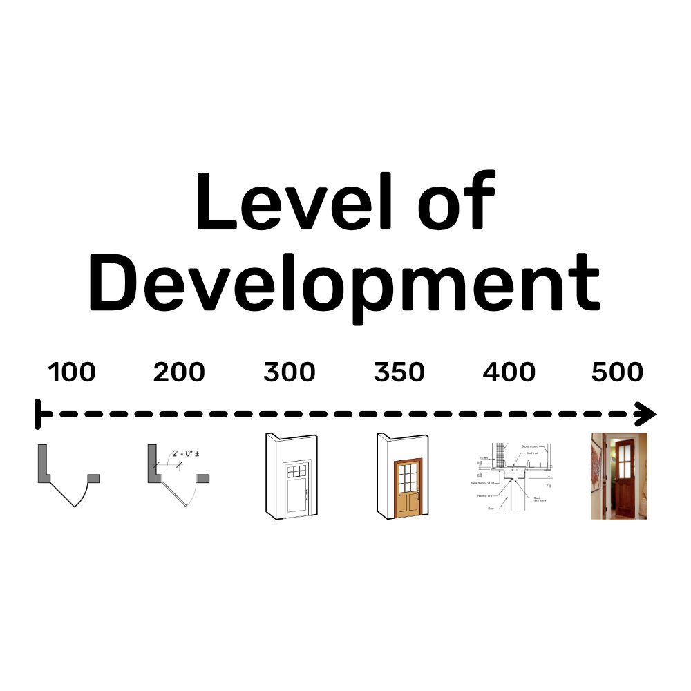
Level of Design/Detail/Development (LOD) assists the AEC industry with articulating a BIM project status through levels of refinement and specifications to clearly communicate and eliminate confusion for faster coordination.
Origins
LOD was introduced by the American Institute of Architects (AIA) in 2008, which defined five development levels for a BIM model. While the concept existed before then, this was the first time it was formalized in the context of BIM. Since then, there is an added sixth level, LOD 350, sandwiched between LOD 300 & 400.
LOD Definition
While I could make my own definitions its best to reference the authoritative BIM Forum directly.
LOD 100 - Conceptual
The Model Element may be graphically represented in the Model with a symbol or other generic representation, but does not satisfy the requirements for LOD 200. Information related to the Model Element (i.e. cost per square foot, tonnage of HVAC, etc.) can be derived from other Model Elements.
Interpretation:
LOD 100 elements are not geometric representations. Examples are information attached to other model elements or symbols showing the existence of a component but not its shape, size, or precise location. Any information derived from LOD 100 elements must be considered approximate.
Example:
This can be anything from a simple had sketch on a napkin to roughed out massing models. Ideally, something that easily interfaces with a BIM software. Like Sketchup or Autodesk FormIt.
LOD 200 - Approximate Geometry
The Model Element is graphically represented within the Model as a generic system, object, or assembly with approximate quantities, size, shape, location, and orientation. Non-graphic information may also be attached to the Model Element.
Interpretation:
At this LOD elements are generic placeholders. They may be recognizable as the components they represent, or they may be volumes for space reservation. Any information derived from LOD 200 elements must be considered approximate.
Example:
SD to DD plans, elevations, and sections with approximate locations and counts of all components for a project.
LOD 300 - Precise Geometry
The Model Element is graphically represented within the Model as a specific system, object or assembly in terms of quantity, size, shape, location, and orientation. Non-graphic information may also be attached to the Model Element.
Interpretation:
The quantity, size, shape, location, and orientation of the element as designed can be measured directly from the model without referring to non-modeled information such as notes or dimension call-outs. The project origin is defined and the element is located accurately with respect to the project origin.
Example:
All objects are accurately modeled and to final dimension along with coordinated disciplines.
LOD 350 - Precise Geometry & Connections
The Model Element is graphically represented within the Model as a specific system, object, or assembly in terms of quantity, size, shape, location, orientation, and interfaces with other building systems. Non-graphic information may also be attached to the Model Element.
Interpretation:
Parts necessary for coordination of the element with nearby or attached elements are modeled. These parts will include such items as supports and connections. The quantity, size, shape, location, and orientation of the element as designed can be measured directly from the model without referring to non-modeled information such as notes or dimension call-outs.
Example:
All objects modeled and details for how objects interface with each other. Also includes notes and non modeled diagrams.
LOD 400 - Fabrication/Construction Ready Geometry
The Model Element is graphically represented within the Model as a specific system, object or assembly in terms of size, shape, location, quantity, and orientation with detailing, fabrication, assembly, and installation information. Non-graphic information may also be attached to the Model Element.
Interpretation:
An LOD 400 element is modeled at sufficient detail and accuracy for fabrication of the represented component. The quantity, size, shape, location, and orientation of the element as designed can be measured directly from the model without referring to non-modeled information such as notes or dimension call-outs.
Example:
Construction documentation that includes final coordinated manufacturer/fabricator information and details.
LOD 500 - As-built
The Model Element is a field verified representation in terms of size, shape, location, quantity, and orientation. Non-graphic information may also be attached to the Model Elements.
Interpretation:
Since LOD 500 relates to field verification and is not an indication of progression to a higher level of model element geometry or non-graphic information, this Specification does not define or illustrate it.
Example:
Finish built stairs.
Below is a table that clearly marks out what the BIM model should be capable of at different LOD’s.
Model Content |
LOD 100 |
LOD 200 |
LOD 300 |
LOD 400 |
LOD 500 |
|---|---|---|---|---|---|
| 3D Model Based Coordination | Site level coordination | Major large object coordination | General object level coordination | Design certinty coordination | N/A |
| 4D Scheduling |
Total project construction duration Pasing of major elements | Time-scaled, ordered appearance of major activities | Time-scaled, ordered appearance of detailed assemblies | Fabrication and assembly detail including construction means and methods (cranes, man-lifts, shoring, etc) | N/A |
| Cost Estimating | Conceptual cost allowance Example $/sf of floor area, $/hospital bed, $/parking stall, etc. Assumptions on future content | Estimated cost based on measurement of generic element (i.e. generic interior wall) | Estimated cost based on measurement of specific assembly (i.e. specific wall type) | Committed purchase price of specific assembly at buyout | Record costs |
| Program Compliance | Gross departmental areas | Specific room requirements | FF&E casework, utility connections | ||
| Sustainable Materials | LEED strategies | Approximate quantities of materials by LEED categories | Precise quantities of materials with percentages of recycled and/or locally purchased materials | Specific manufacturer selections | Purchase documentation |
| Analysis/Simulation | Strategy and performance criteria based on volumes and areas | Conceptual design based on geometry and assumed system types | Approximate simulation based on specific building assemblies and engineered systems | Precise simulation based on specific manufacturer and detailed system components | Commissioning and recording of measured performance |
Why use LOD?
LOD manages risk on projects that require inter-discipline model coordination. Without a clear baseline, it is harder to ensure everyone is on the same page. Engineers will work off of what they believe is final thickness of walls while architects are still in process of dictating final assemblies and opening locations. With LOD’s help, communication and collaboration will become faster and easier, creating space for efficient articulation of design and resources at all stages of development.
LOD in small firms
Smaller firms or firms with smaller projects might be asking, “This is all well and good, but why should I incorporate LOD into my practice? I design small residential/commercial projects, sub-contractors only barely look at my drawings, and no one else but me needs the model.” I agree. LOD is first a baseline development classification, however this does not mean you should reject the intention of the LOD structure.
While most firms have a “baseline” for what should be included on issued drawings at different stages of the design process, this is a separate standard from how detailed a model is developed.

Setting a consistent BIM modeling standard in your office will:
Ensure everyone is on the same page for what to expect for each project. Cut the guess work from having to figure out what happened on previous and new projects.
Keep production cost consistent. Train employees to know the correct max and minimum modeling standard.
Be more competitive with bids. Once your firm has a set standard, or range of standards, it will allow more flexible pricing to match in-house standards.
Cut down on miscommunication between disciplines. Consistent model handoffs, reduces the stop-revise-start cycle.