Add color to detail families!

I recently assisted a customer instructing how to set up color visibility parameters in a detail family. The brief was simple: Three versions, black and white, existing, and color. They all needed to be instance parameters and turn on/off the other attributes if one is checked.
Most users might assume this issue will require more complicated formulas to turn on/off the other colors. Not so! This might be a solution if each of the colored areas were different shapes to begin with, or have several other dependent graphic parameters, along with the need to ensure users do not accidentally forget to turn off a certain parameter.
For users who are interested, here is the formula process for controlling the visibility of three plus objects in a family.
The simply solution is to…not…include formulas or extra parameters. Let me explain. Instead of six parameters, we realistically only need two. Why? This is because each of the graphic filled regions can be layered on top of the other. Therefore, if the colored area is turned on, the existing and white fill region will not be visible since they were generated before the colored filled region. Now you will need to make sure the layers are generated in a sequence or simply select the filled region and rearrange the order. With this in mind, we now only need two parameters instead of six! Since the white will be the default when the other two regions are turned off, the existing and colored regions only need a visibility parameter. Simple right?
Below, are step by step instructions for how to set this up for yourself.
Step 1 – New File
Open an existing detail items family from the Revit library. (Any family will do but this example uses the nominal cut lumber detail family.)
Step 2 – Visibility Graphics

Turn on the dimension and reference plane visibility in the family editor. (Some families have these turned off to keep inexperinced users from accidentally breaking families.)
Go to: View > Graphics > Visibility/Graphics.
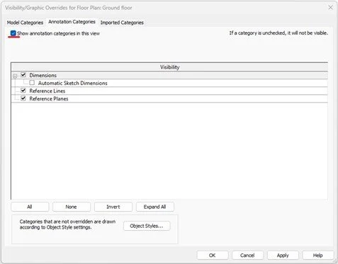
Inside the dialog, navigate to the Annotation Categories tab and ensure the “Show annotation categories in this view” is checked. Select OK to close out the dialog.

Users will now be able to see the set-up dimensions and reference planes that drive the width and height parameters.
Step 3 – Set up filled regions
Go to: Create > Detail > Filled Region
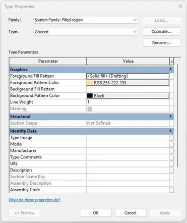
In the Type Properties dialog, set the Foreground Fill Pattern to whatever pattern you desire(we set it to <Solid Filled>). Next adjust the desired color and rename the Type.
Next, select duplicate to create an Existing fill type and follow the same instructions to set up how it should look. Then select OK to close the dialog.
Step 4 – Object Styles
This step is only necessary if users want to show alternative colored lines for “Existing” graphics like in our example.
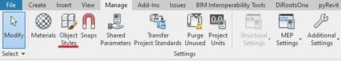
Navigate to: Manage > Settings > Object Styles
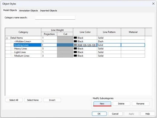
Inside the dialog, under the Model Objects tab, click New under Modify Subcategories.
Create the Existing Lines and set up the line weights, color, and pattern as desired and select OK to close.
Step 5 – Adjusting existing line weights

Edit the existing masking region by selecting the object and going to: Modify | Detail items > Mode > Edit Boundary.
Inside select the boundary lines and change the subcategory to <Invisible lines>, ensure all lines are aligned and locked to the dimensioned reference planes, then select the green check mark to close out the editor.
Next create two new Filled Regions in the view, one is colored and the other is existing. Ensure the lines are set to <Invisible Lines> and they are aligned and locked to dimensioned reference planes.
Step 6 – Filled region visibility parameters

Hover over the filled regions with the cursor and press the Tab button on your keyboard to cycle through to the colored region. Once selected, in the Properties Palette we need to associate a visibility parameter, click on the square along the right side of the Visible parameter.
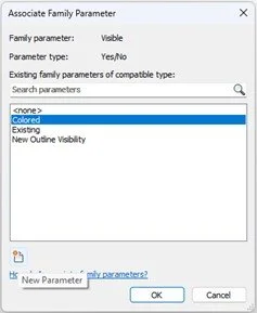
Inside the dialog, create a new parameter called “Colored” by clicking on the New Parameter button in the lower left corner of the dialog.

Inside the Parameter Properties, fill out the name and “Group parameter under.” Set the parameter to Instance and select OK to close. Inside the Associate Family Parameter, select the new parameter and select OK to close.
Follow the same steps for setting up the Existing visibility parameter.
Step 7 – Detail lines and visibility parameters
For this detail family there are three line types used: Heavy Lines, Light Lines, and Existing Lines.
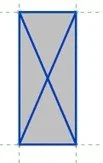
The heavy lines will be used for the outline, light lines are used for the X detail, and the existing lines are used for both types.
First, set the Existing lines and align and lock to the reference planes. Then select all Existing lines and inside the Properties Palette assign the Visible parameter to the “Existing” parameter. This will ensure the existing linework will not be visible if the parameter is unchecked.
Second, repeat the same process but place the Heavy lines for the outline and Light lines for the X. However, these lines will have a different visibility parameter.
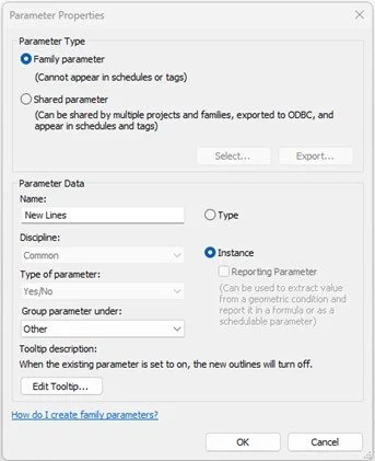
Set up the new parameter called “New Lines” as shown above and select OK.
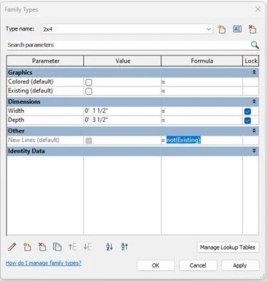
Inside the Family Types dialog, in the New Lines parameter, under the Formula column place the simple formula: not(Existing) and select OK to close. (This formula simply means, when the Existing parameter is checked, the new line work will not be visible and vise-versa. This is only applicable if following Step 4.)
Step 8 – Save file
Check the family by loading the detail into a project file and check and uncheck the parameters to ensure everything works. If everything works, save the file as new to start a new catalogue!
With that we only have three new parameters in this file, two are actively used and one operates in the background without needing to remember. I hope this inspires you to apply this knowledge to other families in your collection.