The Mystery of the Purple Wall: Troubleshooting View Graphics
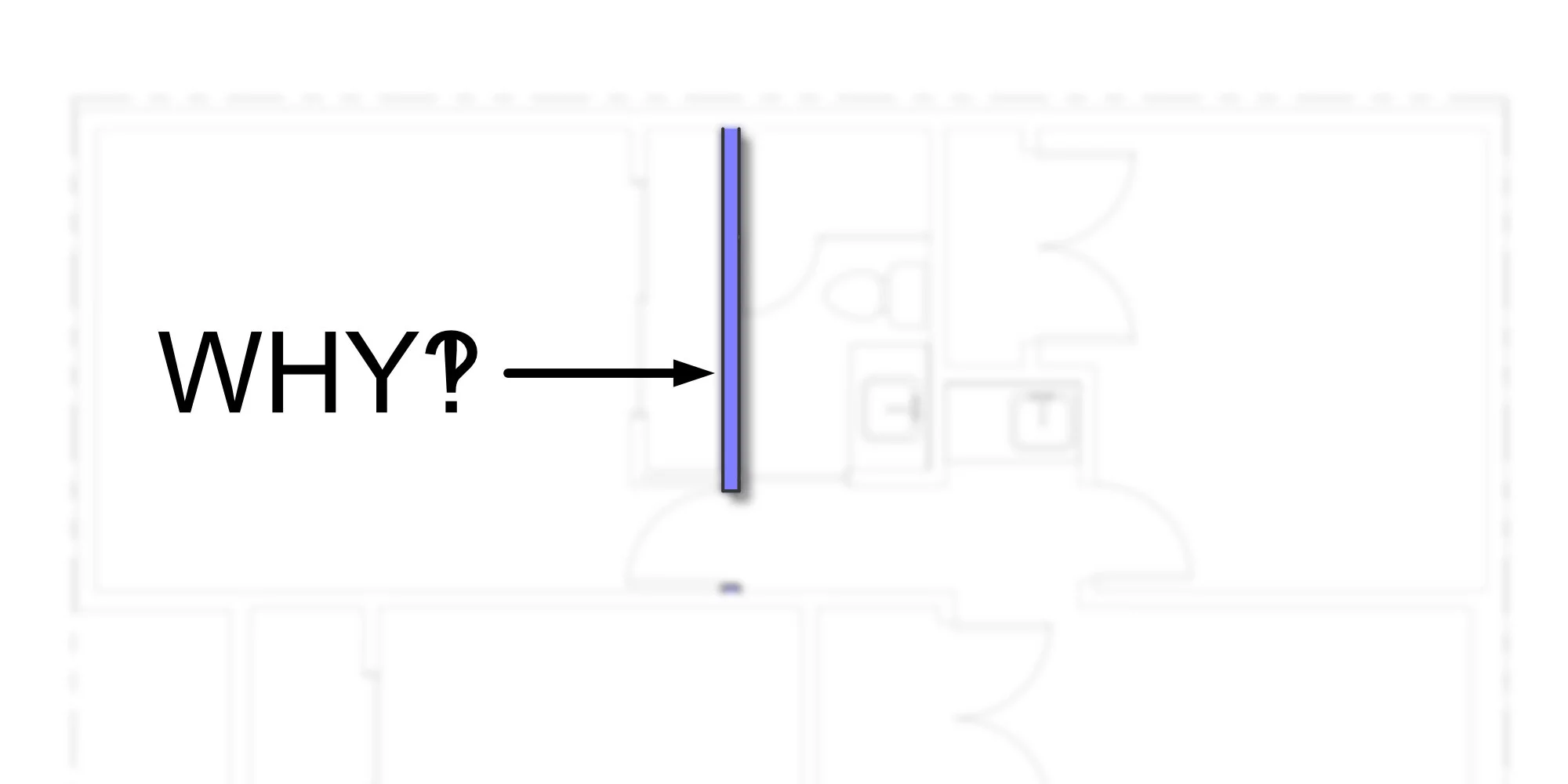
Blame it on the intern. Occasionally you will come across issues like mine. The wall is purple, I do not know who did it and for what purpose but I need to figure out where it was modified in Revit. This can be tricky because Revit has more than one way to modify graphic elements. Some tools affect Revit views globally and some only affect your current view. I will walk you through each graphic override so you too can be a master sleuth at your office. The graphic overrides are organized starting with the most global affect down to element specific affect.
Phasing
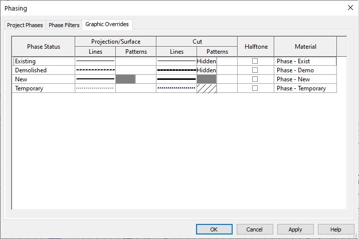
Manage > Phasing > Phases
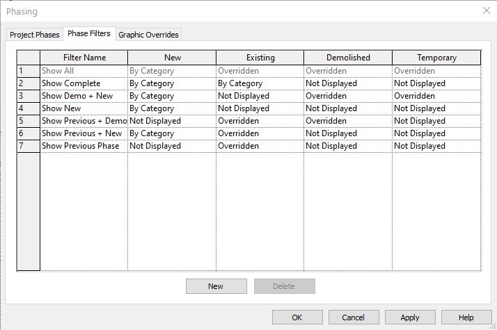
Every model object in Revit is assigned a phase created and demolished. Once a family is placed this is the first stop on the graphics flowchart. Under the graphic overrides tab, you can see how every phase should look on any given, unmodified, view. After you confirmed these settings you will want to check the phase filters tab. Each of the filters should have one of three parameters assigned to each phase: by category, overridden, or not displayed. You simply need to check if the phasing of the object in question is following the phase graphic overrides or is set by category.
Once an office standard has been set you will never have a reason to modify these settings. If you are more interested in phasing I wrote an entire blog post to the topic.
Object Styles
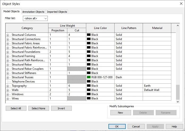
Manage > Settings > Object Styles
At our second stop, we have object styles that control how every family category and subcategory will look globally, in every view, when not set to be overridden by a phase filter. However, object styles are a base line view standard so you will still need to modify views in the visibility graphics to set up how you need objects to look in each view. This is another override tool that should be set as a catch all standard and never modified.
Detail Level

This parameter should be set up inside the family file by assigning modeled objects to detail level visibility settings (e.g. door families > panel, frame, trim, threshold, hardware, etc… should all have a detail level assigned.) and once imported can be controlled by the model detail level inside the project file. If there are parts of a family not showing up correctly this is likely due to improper detail level assignment. This is quite common when you download free families from the web. A quality family will have careful thought put into how an object should present itself at different detail levels. Too much detail at a small scale can make families look dense on plotted sheets.
Assembly families specific type properties graphics

Select wall/floor/roof/ceiling > Properties Palette > Edit Type > Graphics
This graphic override is specific to assembly families (wall/floor/roof/ceiling) but can also be a pesky graphic override to find for a novice. Any changes to this will only affect that specific assembly family. However, this will be overridden by the visibility/graphics override.
This feature is useful if you need to graphically show a wall with a separate hatch pattern or color to identify it as, say, structural or rated assembly. However, this can lead to workflow issues if you forget to modify the visibility graphics of a new view or forget to apply hatching to new wall types. I do not use this feature because I believe all assemblies should look consistent in the project and should be identified by an associated assembly tag with the specified construction assembly for more accurate communication. If specific attention to certain assemblies are required, I prefer to use a key plan as an alternative.
Visibility/Graphics Override

Properties Palette > Graphics > Visibility/Graphics Override > Edit
We are now at the point where the graphic changes made are view specific. Any changes to model object visibility properties will override the general object styles. If anything looks wonky, this is typically where you first find your culprit. The main difference between visibility/graphic overrides and object styles is you can also control cut patterns, transparency, halftone, and lock the detail level of a family category independent of the view detail level.
At this point, you can get quite granular with tweak your drawings but can get a little repetitive and time consuming, especially if you have a multi-story building, to tweak every setting individually. At that point you should begin to incorporate view templates with preset visibility/graphics overrides into your workflow. Trust me, this is a massive time saver to use view templates.
Override graphics display
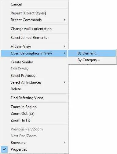
Right click an object > Override Graphics in View > By Element/Category
This is the final graphics override tool you need to review in your quest to fix the interns…short comings. You can modify everything the same way you would in the visibility/graphics override, minus adjusting the detail level, except this will override all other parameters both globally and view specific. The only catch is you are not able to quickly see if a model object is overridden in view unless you notice something is off. This is a quick fix tool, but not sustainable.
So, what was it that made the wall purple? Have you guessed? The wall graphics were overridden in the view by element. It clearly could not have been any of the other graphic overrides but was a good excuse to review the different tiers and methods. Now there are other reasons why a model element is not showing up correctly in a view (e.g. design options, view range, crop regions, or hidden elements in a view [I wrote a separate blog post about this]) however, these are the main tools I review to troubleshoot any weird view graphics issues. If you have a coworker who seems to carelessly modify visibility graphics, send them this as a gentle reminder of graphic override hierarchy.